The objectives of this paper are to develop structural modeling finite element analyze and the optimization of the connecting rod for robust design. Heads with the end-milling cutter.
Pdf Design And Analysis Of A Connecting Rod For The 117kw Six Cylinders Turbocharged Diesel Engine
To this end it is necessary to finely control the volume and geometry of the preform in order to avoid both the flash appearance and the incomplete die filling.
. To geometrically model the connecting rod as per the dimensions generated from the process of design procedure followed. An I-beam is both light. A connecting rod subjected to an axial load W may buckle with x-axis as neutral axis in the plane of motion of the connecting rodor y-axis is a neutral axis.
To determine the size of the crankpinCrank pin diameterSelect the diameter The length of the crank pin Select the In order to crank and connecting rod side as far as possible not. They are used respectively depending on their field of application or use. Connecting rod Structural analysis Titanium Steel Gas load Fatigue FEA 1.
It is connected to the piston by means of a piston pin. Ilia et al 2005 provide the minimum I-beam area for the connecting rod for the 19 L and 22 L engines as 132 mm 2 and 141 mm 2 respectively. Step 2 drilling sm all end hole s with twist drills.
The optimization of this process is carried. The structure of connecting rod was modeled utilized SOLIDWORKS software. It is defined as.
These holes must be parallel. Connecting rod The connecting rod links the piston and the crankshaft. It has a hole at the upper end small end and is connected to the piston by the wrist pin.
Design procedure of connecting rod pdf. One of the important part of the combustion engine is the connecting rod and the main purpose of the connecting rod is to transfer the energy from the pistons to crankshaft and convert the linear reciprocating motion of a piston into the rotary motion of a crankshaft from the viewpoint of functionality. Section of the connecting rod is designed as a strut and the rankine formula is used.
𝜎 1 𝑁 𝑥𝑖µ2 𝑁 𝑖1. Pin-end and crank-end pinholes at the upper and lower ends are machined to permit accurate fitting of bearings. Faces of the connecting rod.
The bearing shells of the big end are made of steel brass or bronze. Connect the piston to the crankshaft and converts the pistons. 𝜎 1 𝑁1 𝑥𝑖µ2 𝑁 𝑖1.
So It is connected to the piston pin or gudgeon pin on one side. PDF A connecting rod basically connects the piston to the crankshaft whilst transmitting power of the combustion from the combustion chamber to rotate. And the larger end is in contact with the crankshaft.
Procedure The connecting rod will be created using Pro-Engineer and AutoCad. The big end of the connecting rod is usually made split in two halves so that it can be mounted easily on the crankpin bearing shells. If the piston pin is.
PDF Design and Simulation of. The connecting rod is considered like both ends hinged for buckling about x-axis and both ends fixed for. This type of connecting rod is most widely used in multi cylinder engine.
Hello friendsHere in this video we will learn about the design procedure of Connecting Rod which is a part of internal combustion engine. The design of connecting rod is checked and analyzed. Romlay Universiti Malaysia Pahang DESIGN OF CONNECTING ROD OF.
A connecting rod consists of a pin-end a shank section and a crank-end as shown in Figure. The objectives of this paper are to develop structural modeling finite element analyze and the optimization of the connecting rod for robust design. Engine that has a function to transmit power released from combustion by the piston to the crankshaft.
Connecting Rod Rectangular and I-Beam Cross-Sections With the assumed shape of the cross section for the connecting rod as shown in Figure 2b the cross sectional area of the I-beam section is 11 t 2. The connecting rods made of aluminium alloy and alloy steel. National Conference in Mechanical Engineering Research and Postgraduate Studies 2 nd NCMER 2010 3-4 December 2010 Faculty of Mechanical Engineering UMP Pekan Kuantan Pahang Malaysia.
Piston to the crankshaft. Abstract A connecting rod is the core component of an IC. The small end is press fit and can swivel in the piston.
Different parts of a Connecting Rod The working model of connecting rod is shown in fig1 small end of connecting rod is in contact with the piston with the help of gudgeon pin. These are the five materials which we use in the connecting rod. Accurate modelling of the con rod design optimisation to reduce stress and implications on changing the geometry.
INTRODUCTION A connecting rod can be of two types H-beam or I-beam or a combination of both. It will also query the stated forces and the validity of the assumptions made on the model conditions and magnitude of the forces in tension. Step 1 mi lling one end face of large and small.
Also it connects reciprocating piston to rotating crankshaft and some other. The small end of the connecting rod is usually made in the form of an eye and is provided with a bush of phosphor bronze. Mild carbon steel Aluminum alloy Alloy cast iron Graphite cast iron and.
To analyze the buckling load which is equivalent stress due to inertia forces acting on each material of. In the one by Takemasu et al. 6 the objective is to design the forging process of a connecting rod with no flash in order to save costs.
The lower end also called as Big end is attached to the crankshaft. 2 It is important to point out that equation 2 represents the population standard deviation and then it requires the entire population. As samples instead of entire population are analyzed the sample standard deviation is employed.
During the combustion process deformation is the most commonly occurring damage in the connecting rods. Structure design and the determination of main dimensions of crankshaft details including includes 6 aspects. Th e step by step procedure for finding out the dimensions of the I-section of the connecting rod is as follows.
This article compares and discusses the various obtained results and selects the best material for the connecting rod. Design decision is integral crankshaft. This paper presents the design connecting rod of internal combustion engine using the topology optimization.
And connected to the crankshaft on the other side so the movement of the piston gives to the crank through the rod. I Calculate the force acting on the connecting ro d. The upper end of the connecting rod is connected to the piston by the piston pin.
The Connecting rods are usually made of. Connecting rod is one of the engine s key components which. To design the connecting rod for a petrol engine so as to determine the section thickness of connecting.
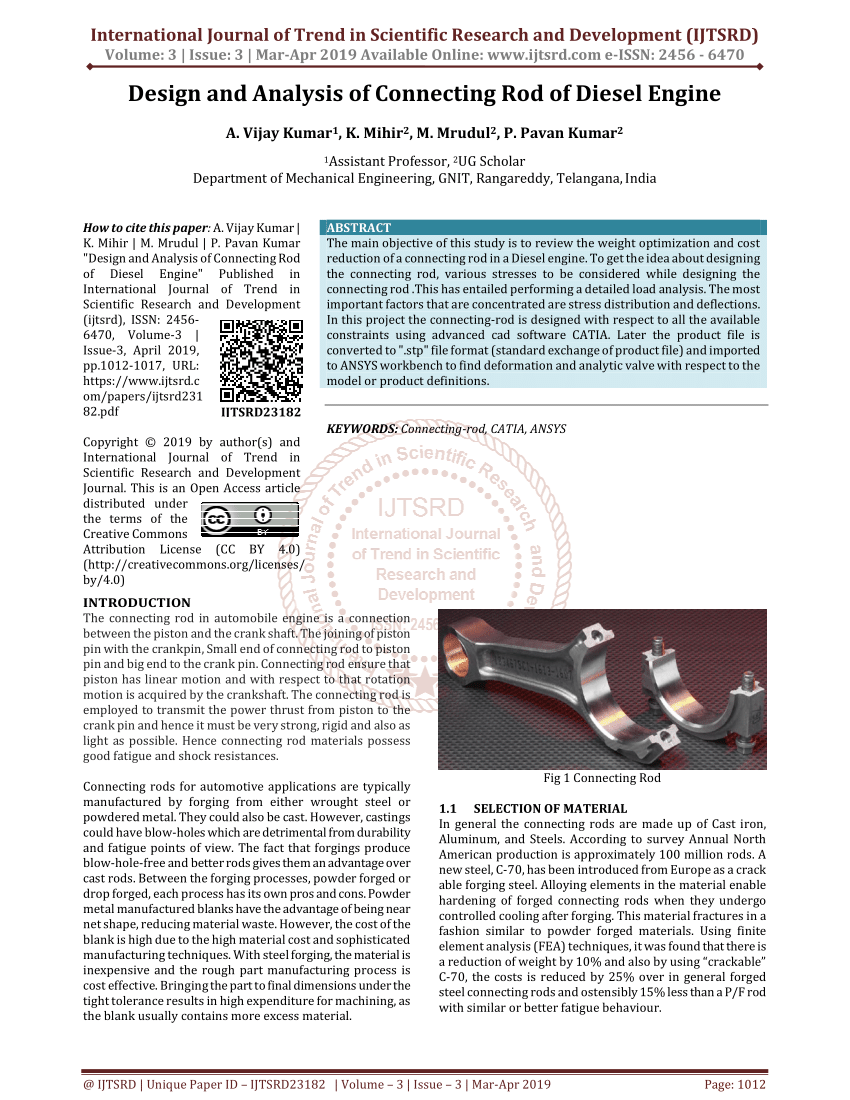
Pdf Design And Analysis Of Connecting Rod Of Diesel Engine

Pdf Design And Analysis Of Connecting Rod Using Forged Steel Leela Krishna Vegi Academia Edu
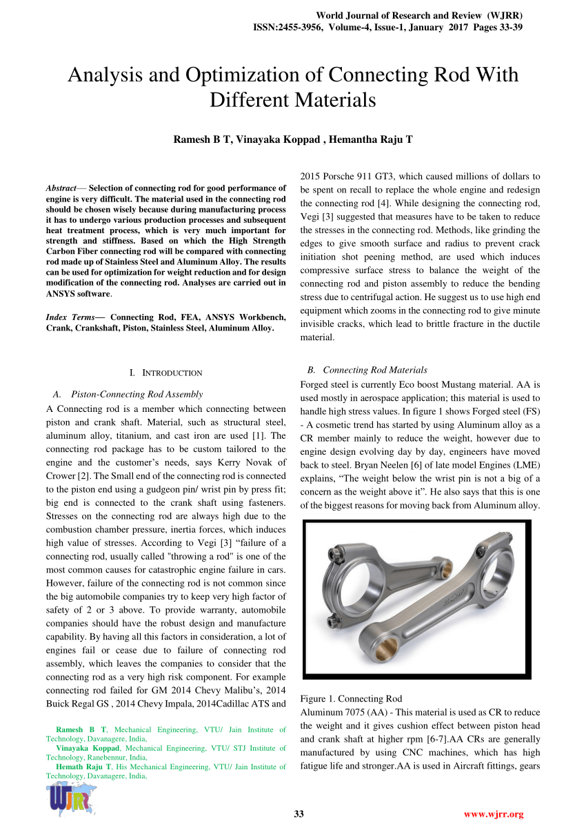
Pdf Analysis And Optimization Of Connecting Rod With Different Materials

Pdf Design Analysis And Optimization Of Various Parameters Of Connecting Rod Using Cae Softwares Semantic Scholar
Pdf Design And Analysis Of Connecting Rod With Modified Materials And Fea Analysis

Pdf Design Of Connecting Rod Of Internal Combustion Engine A Topology Optimization Approach M M Noor Academia Edu
Pdf Design And Analysis Of A Connecting Rod
Pdf Design Considerations For Connecting Rod
0 comments
Post a Comment